Table of Content
- Silanna UV’ Far UV-C & Deep UV-C LEDs now available in 120 or 30 degree viewing angle SMD packages
- How to Make a Simple Electrical Circuit
- Leave a Comment Cancel reply
- OiTec became a New GATE Partner for GOEPEL Electronic
- How to Make an LED Light bulb at Home
- Surge Controlled Voltage Regulation
- How the LED Controller Functions
Below are the different colors and shapes of LED’s and light with incandescent and LED’s tested with the circuit. Energy Storage Battery for Microgrids Market is expected to reach USD... In the housing, there are some locking systems for fixing the LED board, so that the board should be well trapped and does not move.
So I can use 8mm led for better illumination and proper brightness. Capacitor value calculation is not important, but higher value will give better results. You will have to use a transformer for your application. You will have a to buy a 220V to 110V transformer and then you can use it safely for the purpose. For sending an image you can upload it to any “free image hosting site” and provide the link to me. This can be done through an Arduino only, analogue circuit can be too complicated.
Silanna UV’ Far UV-C & Deep UV-C LEDs now available in 120 or 30 degree viewing angle SMD packages
The easiest way to attach the wires is to use electrical tape. Attach the end of one wire to one side of the battery, making sure that the wire maintains contact with the metal of the battery. Repeat with the other wire on the other side of the battery.Alternatively, if you are using a battery snap, snap the end onto the end of a 9-volt battery or the battery pack. A simple electric circuit contains a power source , wires, and a resistor . In a circuit, electrons flow from the battery, through the wires, and into the light bulb. When the bulb receives enough of these electrons it will light up.

Bess Ruff is a Geography PhD student at Florida State University. A circuit is a closed path that electrons flow along to provide power to your home and electronics. The main component of the Transformer Less Power Supply Design for the DIY LED Light Bulb is the X – Rated Capacitor.
How to Make a Simple Electrical Circuit
If your bulb doesn’t light up, check each side of the battery and the screws on the bulb holder to make sure the wires are in contact with metal. Fasten the other end of the wire to the metal screw of the bulb holder. Take the exposed metal end of each wire and bend it into a U-shape. Loosen each screw on the light bulb holder just enough to slip the U-shape of the wire around the screw. Tighten the screw, ensuring that the metal of the wires remains in contact with the screw. First, the main supply is given to the metal film capacitor.
Can anyone Suggest best circuit diagram to control 2 LED’s blinking in 3 Modes i.e. When we press a button both glow continuously, when we press again both LED’s start Blinking & finally when pressed again Alternate blinking of both LEDs. R2 is selected so that it develops 0.6V across itself whenever an over current is detected.
Leave a Comment Cancel reply
Hi Rohith, I am not sure about the capacitor number, you'll need to try it practically to confirm. Actually for 30/40 LEDs, the zener should be a 150V rated. R2 and R3 are already present so no more resistors would be required. Use more number of LED in series to increase the illumination…use at least 60 LEDs to make it bright and safe. Yes you can do that, but the 12V SMPS will need to be above 30 amp rated, or you can even try a 0-12V/50amp transformer for the same after aptly rectifying the output to a pure DC. Alternatively, you an make just two channels each having 50 LEDs, that would make the design even more efficient, cooler and brighter.

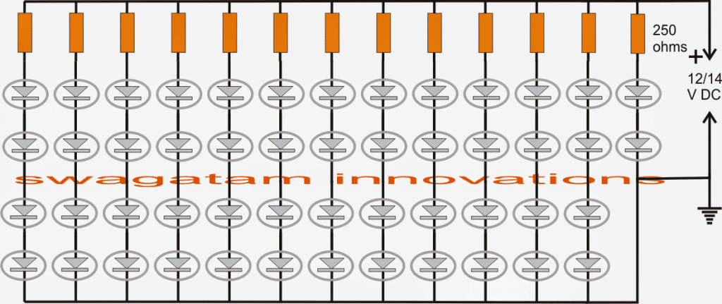
Alternatively the configuration may also be used as a high current transformerless power supply circuit. The above LED control systems have their respective drawbacks and the positives in which the range of operating voltage and the number of LEDs at the output decide the efficiency of the circuit. To be precise we see that basically 40 LEDs have been used which are connected in series. Actually for a 220V input, you could probably invorporate around 90 LEDs in series, and for 120V input around 45 would suffice. White LEDs have especially become very popular due to their mini size, dramatic illuminating capabilities and high efficiency with power consumptions. In one of my earlier post I discussed how to make a super simple LED tube light circuit, here the concept is quite similar but the product is a bit different with its specs.
To build a simple circuit, you will need a power source, 2 insulated wires, a light bulb, and a light bulb holder. A power source can be any type of battery or battery pack. The rest of the materials can be found at your local hardware store.When choosing a light bulb, find one that is around volts so a single battery can power them. The wires will be conducting your electric current from the batteries to the light bulb.
ST is committed to accelerating research & development investments to create technology for... Fix the LED driver PCB by putting it inside the housing, keep in mind that PCB does not move. To fix, you can stick to the hot gun by applying glue. The above circuit will work for both the voltages, however 120V won't support more than 32 LEDs. Parallel srings will result in low illumination, so it's not recommended, you should connect all the LEDs in series only.
Each of the 12 strings must have their own individual series resistor whose value could be around 55 ohms 1/4 watt. My objective with this project was to create a low cost energy saving LED bulb for slum areas. Energy saving bulbs are expensive here in Pakistan. Chinese bulbs rating 5 to 7 Watts costs around 6 to 8 US$ which are not affordable for lower middle class families. Now put the plastic cup that comes with the bulb and close the bulb with it.
The zener is also vulnerable to the current surges, but here it is protected by R3, so nothing to worry. You can use any mobile charger to illuminate the board through a series resistor. Sorry, presently I do not have a WiFi operated dimmer circuit in this blog. Other factors like whether the LEDs are included in parallel or series or whether they need to bedimmed or not, also affects the above typologies.
Also kindly tel me the current output of your circuit. Please provide LED current rating and the mosfet number….I hope the voltage of each LED is 3.3V. Screw the light bulb into its holder until it is tight. If your circuit is hooked up properly, the bulb should light up when fully screwed into its socket.Light bulbs can heat up quickly so be careful when installing and removing the bulb. Take the exposed metal end of one of the wires from the battery pack and bend it into a U-shape.
I've also made your 1W single LED 220V AC circuit. Now I want to attach only single 5mm LED to this 1 watt circuit. Actually I have posted you this requirement in the comment in that 1W circuit page bt maybe it couldn't reach to you or you may angry with me.
ST is committed to accelerating research & development investments to create technology for...
Also getting confused with the number of pins those different transformers has. If it’s a 555 based then you can reduce the timing capacitor value to 680pF and check the response. Good day sir, please for the shunt regulator with transistor tip147, please where can I put led bulb to light up when adjusting to a desired output.


No comments:
Post a Comment